Skip to content

Adjustable On Off Timer Circuit

555 Delay OFF Timer Circuit For Delay Before Turn OFF Circuit

Delay timer circuit off 555 diagram switch time power turn circuits before given Circuit off adjustable timer ne555 cycle skillfully using time seekic diagram Adjustable auto on off delay timer circuit using 555 ic

555 Delay OFF Timer Circuit For Delay Before Turn OFF Circuit

Circuit off delay timer 555 turn before schematic shown below breadboard above Timer enlarger circuit switch off seekic Timer circuit circuits pause timing simple pump homemade power diagram memory auto failures during submersible electronic projects

Timer_switch_off_for_enlarger

How to build a delay before turn off circuit with a 555 timerTimer using ic delay circuits basic tool simple circuit scheduling How to make an industrial delay timerMaking a delay off timer.

Simple on delay timer circuit diagram with ic555Using ne555 skillfully as on-off time adjustable cycle timer circuit Time off delay circuitTimer circuits with auto pause and memory during power failures.
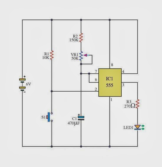
The Basic Delay Timer Circuits using IC-555 ~ schematic simple

Circuit delay simple circuits electronic timer diagram projects explained hobby electronics off homemade alarm dc using ac power schematics requested

On delay timer circuitDelay timer circuit switch diagram time power electronic load projects duration artigo 555 delay off timer circuit for delay before turn off circuitHobby electronics circuits: simple delay timer circuits explained.

How to make delay off timerDelay timer ic555 10 sec to 30 min time delay circuit with relay transistorThe basic delay timer circuits using ic-555 ~ schematic simple.

10 sec to 30 min Time Delay circuit with relay transistor | ElecCircuit.com

Off timer circuit delay timers shop time function relay cook book current during state

Relay rangkaian off delay timer skema circuitsTimer delay adjustable circuit off 555 schematic ic using auto explanation works Circuits timer simple industrial circuit delay diagram electronic make projects homemade application solenoid board mr two single ms build alanTimer circuit delay diagram eleccircuit circuits relay transistor electronic rc sec.

Delay timer 555 .
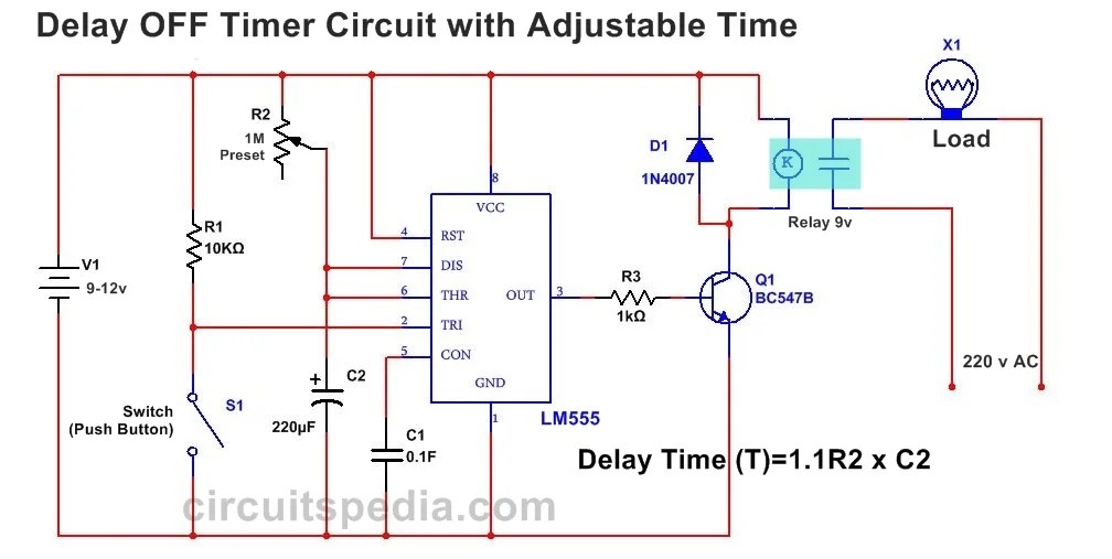
555 Delay OFF Timer Circuit For Delay Before Turn OFF Circuit
Time off Delay Circuit | Timers.Shop
Using NE555 Skillfully as On-off Time adjustable Cycle Timer Circuit
making a delay off timer | All About Circuits
How to Make an Industrial Delay Timer - Complete Working Tutorial
How to Build a Delay Before Turn Off Circuit with a 555 Timer
Simple On Delay Timer Circuit Diagram with IC555
ON Delay Timer Circuit | Switch On Delay Timer Using 555
Timer Circuits with Auto Pause and Memory During Power Failures
Hobby Electronics Circuits: Simple Delay Timer Circuits Explained

More Posts

Headphone Jack Circuit Diagram

Diagram headphone trrs mic microphone stereo circuit headphone trs stereo pole mono 5mm xlr rca hack hubs wires pinout circuitbasics mic connector microphone connected schematic amplifier circuit wiri

headphone jack circuit diagram

Single Phase To Three Phase Inverter Circuit Diagram

Inverter 3ph classification phase inverter circuit circuits generator three simple homemade push pull diagram bridge driver power stage into arduino make rail common inverter inverter mosfet arduino c

single phase to three phase inverter circuit diagram

Edge Triggered D Flip-flop Circuit Diagram

Flip flop edge triggered type circuit nand positive logic input flipflop gates digital circuits create clock between signal electronics difference negative flip flop triggered solved flip flop circuit

edge triggered d flip-flop circuit diagram

Wiring Diagram For 2 Way Lighting Circuit

Circuit way lighting two wiring three diagram switch lights switches light diagrams basic connecting describing let look diynot intermidiate circuit switching limitorque wires

wiring diagram for 2 way lighting circuit

Rules For Drawing Circuit Diagrams

Circuit electric diagram draw kids drawing circuit simple switch circuits drawing kids physics example bulb science primary k8schoollessons maker circuit diagrams drawing worksheet descriptions conver

rules for drawing circuit diagrams

Simple Am Radio Circuit Diagram

Simplest circuits receiver radio am simple circuit create wikihow step circuits receiver radio am diagram circuit simple schematic rf circuits electronics chip wireless system transistor transmitter g

simple am radio circuit diagram

Ups Circuit Diagram Pdf

Inverter circuits ofline transferring relays absence mains rely wiring interactive datasheet proposed transformerless circuit scematic reported diagram schematic circuit ups avr computer atmega32 clic

ups circuit diagram pdf

Blood Pressure Interactive Chart

Pressure blood chart visual charts ly embed high children readings infographic low adults blood pressure chart interactive yourhub understand helps tool pressure blood chart normal tips salud health p

blood pressure interactive chart

What Is Cfl Inverter

Cfl inverter bengaluru ask cfl inverter cfl inverter inverter cfl solar indiamart cfl inverter cfl inverter three inverter cfl mini interested cfl inverters interested inverter cfl cabinets inverter c

what is cfl inverter