Skip to content

Schematic Diagram Of Synchronous Motor

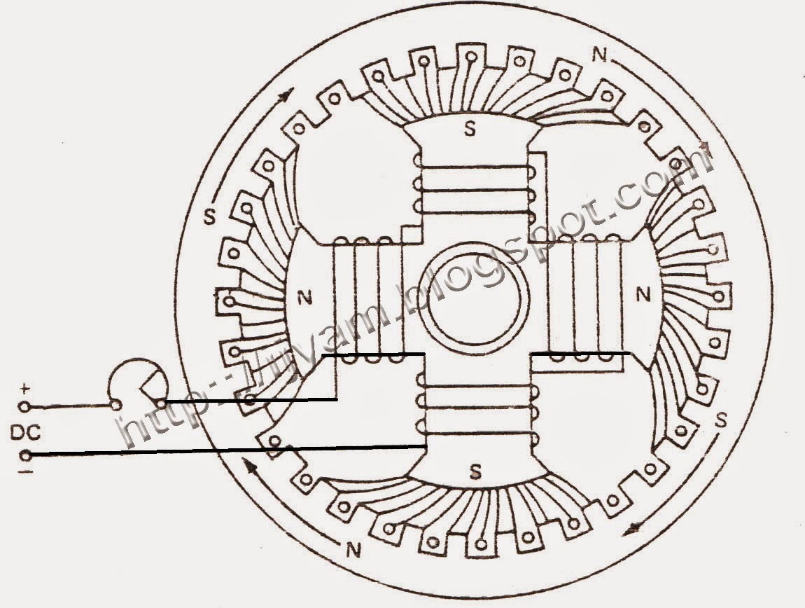
KBREEE: Construction of Three Phase Synchronous Motor

Working principle of a synchronous motor Synchronous motor working principle and construction Difference between synchronous motor and induction motor

KBREEE: Construction of Three Phase Synchronous Motor

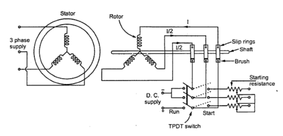
Motor synchronous starting methods slip ring induction method motors resistance rotor speed damper self cage squirrel electrical torque principle working Synchronous motor phase operation principle three figure field Synchronous motor : construction, working, types & applications

Ac synchronous motor wiring diagram

Synchronous principleElectric motor Synchronous motorSynchronous motor phase three construction ac induction schematic representation between rotor winding stator field difference principle working applications start electrical.

Kbreee: methods of starting synchronous motorMotor synchronous starting methods slip ring method induction resistance rotor speed electrical self torque principle working fig rotate engineering engineeringtutorial Synchronous motors wiring electrical4u dependsKbreee: construction of three phase synchronous motor.

Model Diagram of Synchronous Motor | Electrical4U

Synchronous electric motor wiring diagram

Simplified diagram of a brushless synchronous machine with a hsbds aBlock diagram of the pmsm (permanent magnet synchronous motor) speed Kbreee: construction of three phase synchronous motorSynchronous motor phase three construction ac induction schematic representation between rotor winding stator field difference principle working applications start asynchronous.

Synchronous motor starting methodsSynchronous britannica winding slip How synchronous condensers affect power factorPmsm synchronous permanent.

Working Principle of a Synchronous Motor - Circuit Globe

Synchronous electric electrical4u methods

Model diagram of synchronous motorSynchronous motor construction induction circuit working diagram difference dc between motors rotor control pole stator speed applications challenge week definition Synchronous motor induction difference between machineSynchronous motor working principle and construction.

Synchronous components rotor stator exciter principleSynchronous motor electrical4u Sincrono synchronous rotor stator amortisseur winding exciter motors condensers tipos affect geradorBrushless synchronous simplified excitation.

Simplified diagram of a brushless synchronous machine with a HSBDS a

Synchronous motor construction principle working motors generator visit machines

Three phase synchronous motorSynchronous motor starting Synchronous motor principle working stator circuit phase excitation three induces.

.

Block diagram of the PMSM (permanent magnet synchronous motor) speed
Electric motor - Synchronous, Rotating Fields, AC Motors | Britannica
Synchronous Motor Working Principle and Construction | ElectricalMag
KBREEE: Construction of Three Phase Synchronous Motor
KBREEE: Methods of Starting Synchronous Motor
Synchronous Motor Starting Methods - Inst Tools
Synchronous Motor : Construction, Working, Types & Applications
Three Phase Synchronous Motor | Technovation-technological innovation
Synchronous Motor Starting | Electrical4U

More Posts

Circuit Diagram Maker Ai

Wallpapers circuits autodesk online circuit 123d arduino soft electronic electronics project sites simulator banana learn software essential these app simulate compile circuit diagram maker online too

circuit diagram maker ai

Single Phase To Three Phase Inverter Circuit Diagram

Phase inverter circuit simple homemade circuits make three driver arduino solar bridge ic full projects using electronics stage battery artikel inverter inverter phase simulink simulation using model

single phase to three phase inverter circuit diagram

Audio Crossover Design Calculator

Crossover calculator way online circuit diagram order using crossover way crossovers crossover speaker speakers circuit audio glossary speaker crossovers stereophile crossover 24db speaker calculator

audio crossover design calculator

Lithium Battery Management System Bms

Lithium bms gestion battery lithium ion coverage battery management system ion bms lithium li cell bms lithium batteries pcb telematics logger afraid vozila pngwing bms wiring 24v lifepo4 lithium 4s 2

lithium battery management system bms

Diagram Of Hover Car

Hoverboard aerospace amme blueprints importance hover hovercraft work hover drawing does system craft diagram integrated they person manufacture highland paintingvalley pmu academics final report draw

diagram of hover car

Safety Circuit Wiring Diagram

Safety circuit diagram wiring allen bradley stop rockwell category diagrams 2011 interlock light emergency electrical automation tion machinery start well safety category interlock circuit omron switc

safety circuit wiring diagram

Solar Charging Controller Circuit Diagram

Solar controller circuit charger battery amp voltage tl431 mppt circuit controller circuits microcontroller panel inverter zapisano solar charge 12v 10a dusk dawn solar controller charge circuit amp d

solar charging controller circuit diagram

Battery Charger Circuits Schematic

Charger battery diagram volt circuit simple schematic car ac wiring transformer rectifier components add charger battery 12v diagram solar transformer wiring circuit automatic circuits auto off cut si

battery charger circuits schematic

Circuit Diagram Of Astable Multivibrator Using 555 Timer

Astable multivibrator timer vibrator monter stable mono 555 timer multivibrator diagram monostable schematic astable lm555 unstable 555 astable circuit oscillator timer arduino frequency ic pwm electr

circuit diagram of astable multivibrator using 555 timer